Robots are beginning to be used everywhere, in every sphere of life, making humans’ lives easier then ever before. Why do we need robotic machines, you ask? Well, think about the multitude of uses for a robot, in places and situations it is either difficult or dangerous for a human to be in, for example, in construction sites, mines, oil wells, the list goes on indefinitely. Build a robotic arm, a mini-version of what could soon be used as automated cranes, etc, all on your own, from this tutorial!
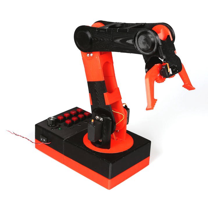
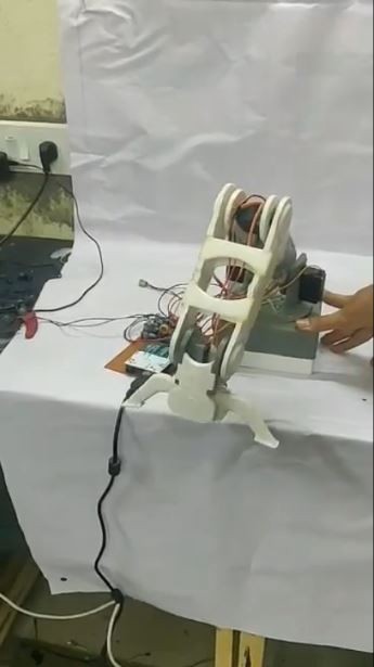
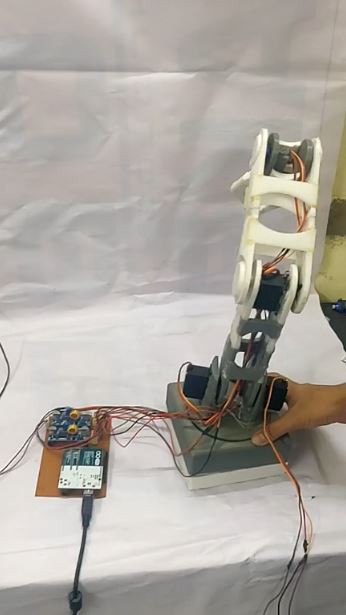
This arm has three servo-controlled joints, plus a rotating base and gripper. The arm is controlled by a series of buttons that connect to an Arduino Uno hidden in the base. A simple circuit makes connecting the servos and buttons to the Arduino easy and makes set-up and assembly very quick.
Components Required
- Arduino Uno
- Standard servos (4x)
- Micro servos (2x)
- Momentary push buttons (8x)
- On/off switch
- Potentiometer and knob
- Green LED
- Printed Circuit Board
- 10k Ohm Resistor (8x)
- 220 Ohm Resistor
- Wires, nuts & bolts
- A 3D printer
- 1kg roll of PLA filament
- Power supply, capable of 2A
Step 1 - Printing the Parts
The arm is about 20 inches long, so it takes a lot of time and material to print. The parts are sized to fit on the bed of the printer, and some can be printed together on the same platform to save time. Most of the parts have “flat” sides that should face the platform. Many of them also have fairly delicate tabs for holding the cables, so take care while removing the raft and support material. Here is a link to help you get the hang of 3-D printing, and make your own design for the arm.
Step 2 - Arduino Code
The Arduino code for controlling the servos is very straightforward. The joints and gripper servos are controlled by a pair of buttons that increase or decrease the servos’ positions by one step. The base is connected to a potentiometer that is mapped to its rotation. The same physical setup can be used with different codes to have the arm do simple automated tasks. (note that there is no positioning feedback, so the accuracy of the arm is limited by the accuracy of the servos). Here is a sample code that can be used.
Step 3 - Extend servo cables
Since the servos will be positioned at various points along the arm, the cables need to be extended. Simply cut the cable and solder in an extension between the servo and the connector. Attach the required type and number of servos according to your design of the robotic arm, wherever necessary.
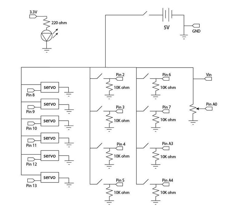
Step 4 - Build the circuit board
The circuit board for the arm is mostly a method for efficiently routing the various wires and signals, rather than a way of adding more components. Start with the resistors, then the various connectors (note that some of them are female and some male). Finally, solder in the connections.
Step 5 - Build your parts
Build your gripper, your lower and middle segments, attach the required servos to the segments, and route the cables. Make sure there is enough slack for moving joints. Attach the arm to the base, and complete building the base.
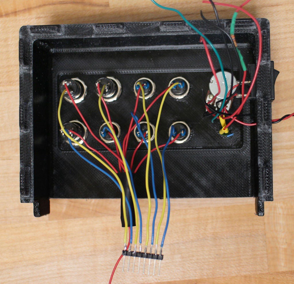
Step 6 - Make the control panel
The control panel has 8 buttons, a potentiometer, an LED, and an on/off switch. It’s easiest to solder leads to all the parts before attaching them to the base (color code the wires: red = power, black = GND, anything else = signal). In addition, add a 220 Ohm resistor to the end of the LED’s positive lead.
Step 7 - Add the circuit
Plug the cables from the control panel into the circuit. The header goes to the row of female connectors just under the resistors (the one below that will go to the Arduino). The 5V from the potentiometer and the buttons go to the 5V headers. Ground from the potentiometer, the LED, and the black wire go to the GND headers.
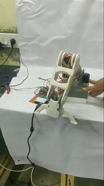
Step 8 - Plug and play!
Plug in the arduino to the servos, close up the base circuit and play!
 |  |  |