Tutorials
Introduction To Gears
No good robot can ever be built without gears. As such, a good understanding of how gears affect parameters such as torque and velocity are very important.
- Mechanical Advantage, Torque vs. Rotational Velocity
Gears work on the principle of mechanical advantage. This means that by using different gear diameters, you can exchange between rotational (or translational) velocity and torque.
As with all motors, by looking at the motor datasheet you can determine the output velocity and torque of your motor. But unfortunately for robots, motors commercially available do not normally have a desirable speed to torque ratio(the main exception being servos and high torque motors with built in gearboxes). For example, do you really want your robot wheels to rotate at 10,000 rpm at low torques? In robotics, torque is better than speed.
With gears, it is possible to exchange the high velocity with a better torque. This exchange happens with a very simple equation that you can calculate:
Torque_Old * Velocity_Old = Torque_New * Velocity_New
- Direction of Gear Rotation
When designing gear setup it should understand how gearing changes the rotation direction of your output. Two gears touching will always be counter rotation, meaning if one rotates clockwise, the other will always rotate counterclockwise. But what if there is a chain of say 6 gears touching? The rule is, an odd numbers of gears always rotates in the same direction, and even numbers of gears are counter-rotational.
Gear Types
All gears, no matter the type, work on the same principles above. However the different types let you accomplish different things. Some types of gears have high efficiencies, or high gearing ratios, or work at different angles, for example. Below are the main common types. This is not a complete list. It is also possible to have a combination in types.
Note: The efficiencies listed are only typical. Because of many other factors could be present, the listed efficiencies should only be used as a guide. Often manufacturers will give you expected efficiencies in the datasheets for their gears. Remember, wear and lubrication will also dramatically affect gear efficiencies.
Spur Gears (~90% efficiency)
Spur gears are the most commonly used gears due to their simplicity and the fact that they have the highest possible efficiency of all gear types. Not recommended for very high loads as gear teeth can break more easily.
Helical Gears (~80% efficiency)
Helical gears operate just like spur gears, but offer smoother operation. You can also optionally operate them at an angle, too. Due to the complex shape, they are generally expensive.
Sproket Gears With Chains (~80% efficiency)
Two gears with a chain can be considered as three separate gears. Since there is an odd number, the rotation direction is the same. They operate basically like spur gears, but due to increased contact area there is increased friction (hence lower efficiency).
Rack and Pinion (~90% efficiency)
Rack and Pinion is the type of gearing found in steering systems. This gearing is great for converting rotational motion into translational.
Suspension systems
When building a robot you’d like it to be as simple as possible. Suspension system may be required in following situations.
your robot travels at high speed on rough terrain
When traveling on rough terrain, your robot is likely to bounce quite a lot. This can wreak havoc on sensor data, joints, and potentially damage things like gears.
your robot has more than 3 wheels
Unlike three points, four points are not guaranteed to always be on a plane. If the terrain is uneven, such as if there were cracks in the ground or small objects to climb over, one of the wheels will lift off the ground. This will create a wobble in your robot, and potentially be a tipping hazard.
Types Of Suspension
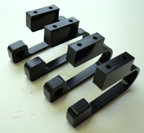
Motor suspension
The long beams attached to the small wheels. These beams are designed to deflect to be perfectly horizontal under the full weight of the robot. When the terrain under it changes, the deflection changes to conform with it. This is what the finished design looks like:
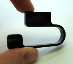
Wheel Suspension System
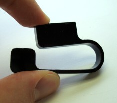
Using a similar design process as the above suspension system, a single part wheel with a built in suspension system can be created.
And in real life:
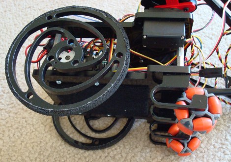
Look carefully at the large round wheels on the left, and the orange wheels on the right. They both single part suspension system design.
Here is what the completed wheel looks like:

A perfectly cut wheel has very little friction. To improve traction, around the edges of the wheel rubber grip can be added.