Introduction
This is a small tutorial on how to make a control box for a simple Differential Drive containing four single push buttons (Forward(F), Backward(B), Left(L), Right(R). One switch for each of them)
Materials Required
- Push Buttons x 4
- PCB(small) x 1
- Relays(6V or 12V) x 4
- Diodes(Small) x 8
- Relimates(2 pin) x 2
- Relimate(5 pin) x 1
- 12V power supply and 6V power supply (If using a 6V relay)
Logic
Basically we need to make a H-bridge kind of working circuit for each motor. The circuit diagram for the relay circuit is as given below :
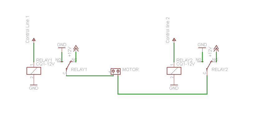
Here the pole (common) of each relay is connected to the terminals of the MOTOR. The pole is connected to two terminals- the NC and NO.
Here, the NC terminal of both the relays have been connected to 12 V and the NO of both have been grounded.
Clearly, when the relay isn’t activated, the pole is at 12 V and when the relay is activated, the pole is ground.
When the relays are in NC state, then both terminals of the MOTOR are connected to +12V and thus, the MOTOR remains in stall condition.
When one of the relays is activated say relay 1, the pole-1 is connected to the ground (NO) while pole-2 is still connected to 12 V (NC). Hence, the potential developed enables the motor to run in one direction.
Similarly, when relay 1 is in NC stated and relay 2 is activated, the motor runs in the opposite direction.
This way, the circuit of the motor is complete and by controlling the relays with different control line the MOTOR’s direction of rotation can be controlled.
Push Button Circuit
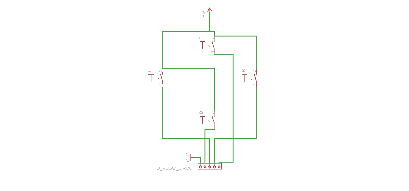
This is the Circuit of the four push buttons will be in the controlling person’s hands.
The Controller Circuit
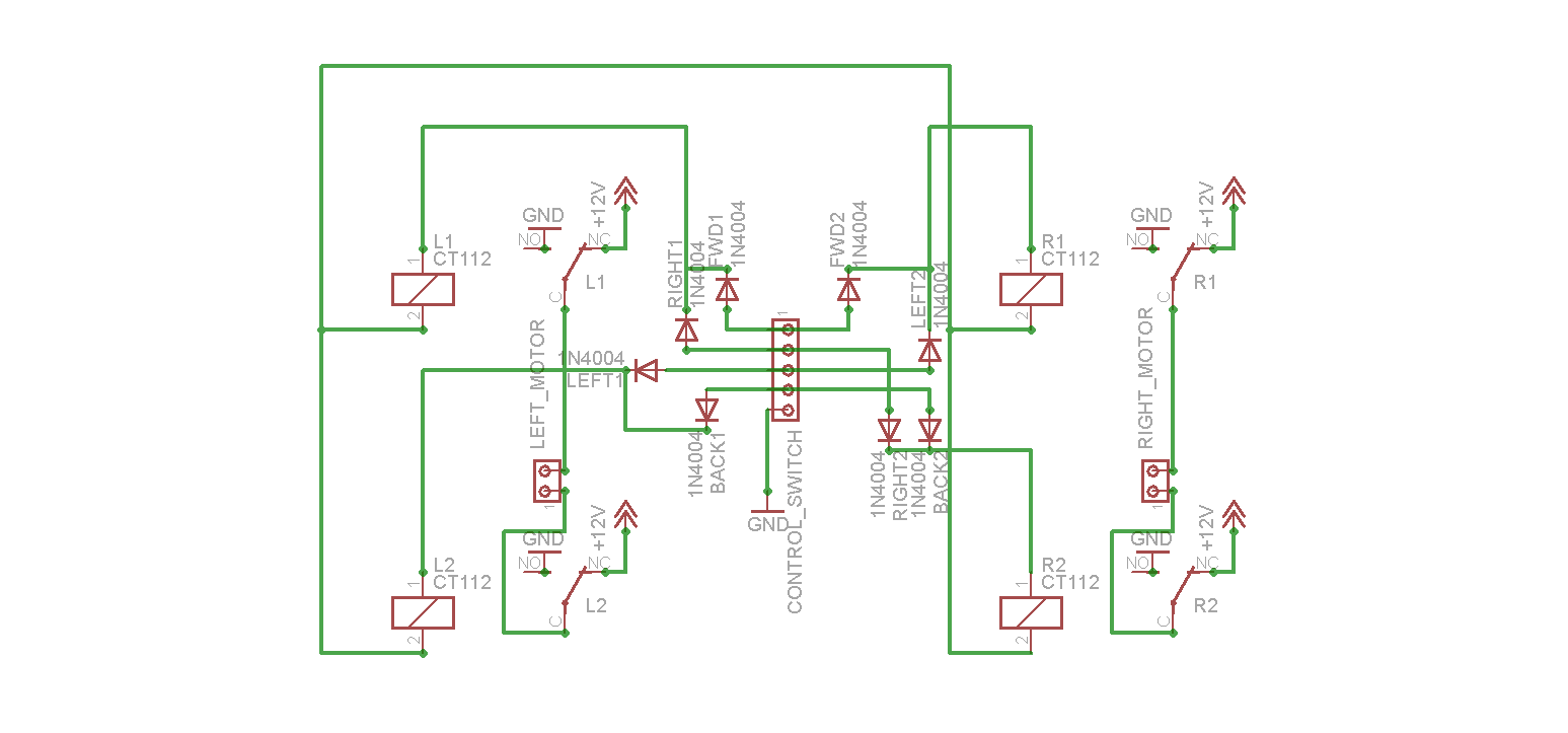
How do we control the motor ?
We saw that we created a relay circuit to control the rotation of the MOTOR by activating a particular relay at a time.
Now we want the power coming from the push buttons to control the motor movement.
The relays R1 and R2 are the relays controlling the Right MOTOR and the relays L1 and L2 are are controlling the Left MOTOR.
The connector from the Push Button circuit is connected to the controller circuit as shown. Now the push buttons F,R,L,B will govern which relays will be active so as to achieve the required movement in the differential drive.
It is assumed that when R1 (1) is NC and R2 is activated (0) then the Right MOTOR moves in forward direction and when R1 (0) is activated and R2 is NC(1), the motor moves in backward direction. Similar is the case with Left MOTOR.
FORWARD : Left MOTOR : forward & Right Motor : forward
Therefore F needs to activate L2 and R2
BACKWARD : Left MOTOR : backward & Right Motor : backward
Therefore B needs to activate L1 and R1
LEFT : Left MOTOR : backward & Right Motor : forward
Therefore L needs to activate L1 and R2
RIGHT : Left MOTOR : forward & Right Motor : backward
Therefore R needs to activate L2 and R1
Truth Table for the connections:
| State | R1 | R2 | L1 | L2 |
|---|---|---|---|---|
| Forward(F) | 1 | 0 | 1 | 0 |
| Backward(B) | 0 | 1 | 0 | 1 |
| Left(L) | 1 | 0 | 0 | 1 |
| Right(R) | 0 | 1 | 1 | 0 |
The Final Control Box
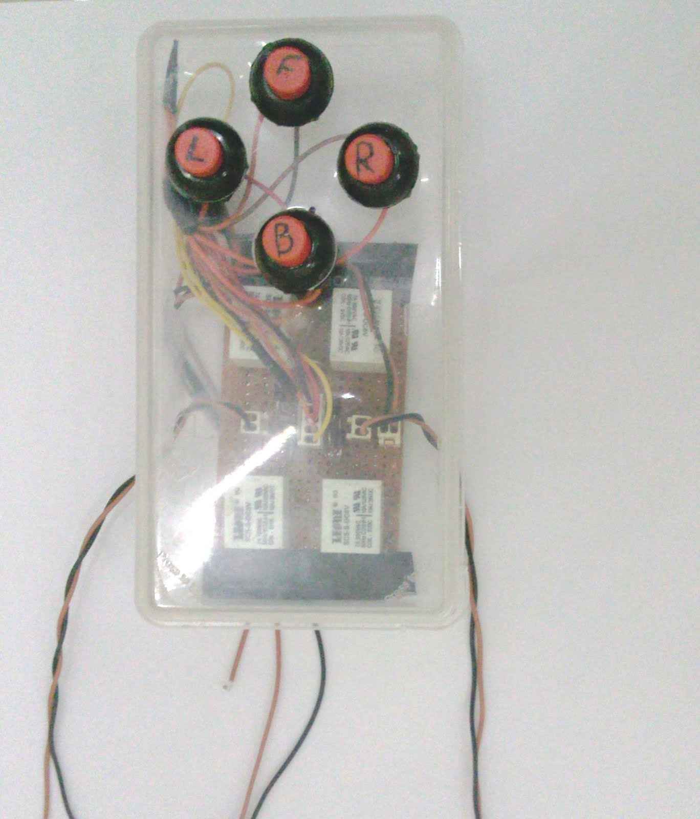
Here is an image of a complete control circuit. 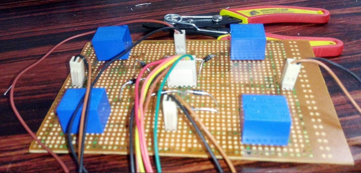
Why Diodes?
If we directly connect the output from push buttons to relays without the diodes, effectively every relay and all the push buttons get shorted so the diodes help to refrain current going from one push button to other push button
After putting the diodes, your control box is ready for providing the gaming experience!!!
Bonus
If you press L then the robot will take a zero degree Left turn and press R then the robot will take zero degree right turn. But, if you press F and R together then R1=1, R2=1 and L1=1 which means that it would simply take a right turn. All the combinations of F+L, B+R, B+L are also possible. If you press F and B together, then both the motors will stop. This is an additional feature in the four push button control box.