Video Tutorial
Introduction
While writing Image Processing codes for applications in robotics, the idea is that the code will process the camera feed as input, and, based on the situation, will give instructions to the microcontroller which is controlling the robot, so as to make it move in a particular direction or perform a particular action. All of this is implemented through the same Visual Studio application, whose final output is a simple character, which serves as the directions for the microcontroller. The communication between the processor, or the laptop, and the microcontroller, is carried out by the implementation of USART or Universal Synchronous Asynchronous Receiver Transmitter, which is a standard protocol for serial data transfer.
For more information on USART, please see the relevant tutorial that have been made for it here.
Connections
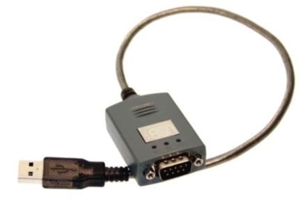
It is required, for the purpose of serial communication, to connect the computer to the microcontroller. In older systems which had a serial/parallel port, this could have been done directly, but nowadays it must be done through USB. So first we utilize something called a USB-to-serial converter which has one end connected to the USB port of the computer, and the other as the male part of a serial pin connection. It looks like this:
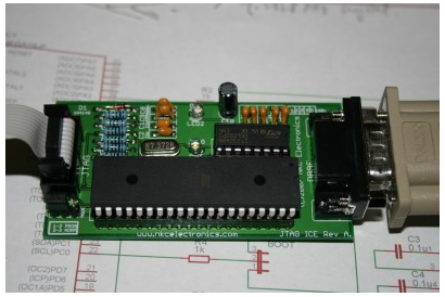
Thereafter, another connector is used which has the female part of the serial pin connection, and at the other end, is connected to the development board for the microcontroller of the robot. Here it is:
It is also to be noted that we may also use direct USB-to-UART connections, and also wireless connections using Bluetooth devices.
Sending Data
Once we have linked our computer to the microcontroller via the connections we discussed earlier, we need to be able to send instructions to it through our code. In our project that we shall use for our Image Processing application in robotics, we have to include files and use certain functions for starting the serial communication device, and then sending data to the microcontroller through the device. We use files that have already been made for this purpose. These are:
- tserial.h – A header file for starting the serial device
- tserial.cpp – The C++ program that actually initializes the device
- bot_control.h – The file which contains the definitions of the functions which shall be used for the purpose of serial communication [send_data(), startDevice(), stopDevice() etc]
These files are available for download from our website. After being downloaded, they need to be included in the Visual Studio project you are using. What you need to do is gather all these three files in a directory and add the path of that directory in Project->
Sample Program
The program below is a standard one which shows how to send characters through the serial communication device, via the code in your Visual Studio project.
Understanding the Code
The initial directives at the top are necessary for properly using the various functions for serial communication. In this program there is no image processing part, but in the final project you use, you will have to include these directives along with the ones you have done for accessing the OpenCV library. The variable comm is an object of the class serial, which is defined in the bot_control.h file. This class has the member functions which we need to access for starting and closing the communication device, among other tasks.
Inside the main function, the user is first asked for the input – the character to be sent through the serial port. Then the serial device is started using the startDevice() function. The first parameter of this function is the name of the COM port that has the USB-to-serial device connected to it. As mentioned, this can be accessed by going to the Device Manager and checking the specifications of the device from there. The second parameter is an integer which is the baud-rate or the data transfer rate for the communication protocol. Please refer again to the tutorial on USART for a deeper understanding of the baud rate and the significance of its value. Then we invoke the send_data() function through the object comm to send the character stored in data through the device. After this we close the device using the stopDevice() function.
This is just a sample program which accepts the input as a character and sends that. In the final image processing program you make, there will be a lot of other functions and code snippets in the program which deal with the image processing and the algorithm of the problem in general. But the essential method for sending data will be the same. In the final program that you write, you will have to include all of these files, declare an object of the class serial and somewhere in your code, specify the initialization of the serial communication device. Thereafter, based on the appropriate situation you will have to send a particular character through the send_data() function. At the end of the program you will have to close the device.
Microcontroller Code
The microcontroller on the robot receives instructions from the processor in the form of characters, and, based on those instructions, sends signals to the motor drivers which make the motors rotate in a particular manner. For more details on how this is done, do refer to the tutorials on motor drivers and microcontrollers.
For the purpose of a demonstration, we will show the sample code for WSAD robot, which basically means a robot that can move forward and back, and turn left and right, when the keys w, s, a and d respectively, are pressed – the basic movements of a differential drive.
The code for this will be better understood after a look into the programming of a microcontroller. In general, however, the code specifies the setting of certain values and registers that are necessary for receiving data sent by the processor and specifying outputs to the motor driver. Then we start an infinite loop, so as to run this for as long as the code is executing. Inside, right at the start, the code directs the microcontroller to wait for the character being sent to be received by the variable data.
Thereafter, based on the value of data, a particular output is sent to the PORT B of the microcontroller, to the first 4 pins of which the motor driver has been assumed to be connected. Based on these outputs sent, the robot moves forward and backwards, and turns left and right.