Overview
A stepper motor is a brushless, synchronous electric motor that converts digital pulses into mechanical shaft rotation. Stepper Motors work under a very similar principle to DC motors, except they have many coils instead of just one. So to operate a stepper motor, one must activate these different coils in particular patterns to generate motor rotation. So stepper motors need to be sent patterned commands to rotate. These commands are sent as high and low logic over several lines, and must be pulsed in a particular order and combination.
Every revolution of the stepper motor is divided into a discrete number of steps, in many cases 200 steps, and the motor must be sent a separate pulse for each step. The stepper motor can only take one step at a time and each step is the same size. Since each pulse causes the motor to rotate a precise angle, usually 1.8°, the motor’s position can be controlled without any feedback mechanism. As the digital pulses increase in frequency, the step movement changes into continuous rotation, with the speed of rotation directly proportional to the frequency of the pulses. However external torque can force movement to a different step, invalidating feedback. Therefore external torque must never exceed the holding torque of a stepper.
Stepper Motor Advantages
- The rotation angle of the motor is proportional to the input pulse.
- The motor has full torque at standstill (if the windings are energized).
- Precise positioning and repeatability of movement since good stepper motors have an accuracy of 3 to 5% of a step and this error is non-cumulative from one step to the next.
- Excellent response to starting/stopping/reversing.
- Very reliable since there are no contact brushes in the motor. Therefore the life of the step motor is simply dependant on the life of the bearing.
- The stepper motors response to digital input pulses provides open-loop control, making the motor simpler and less costly to control.
- It is possible to achieve very low speed synchronous rotation with a load that is directly coupled to the shaft.
- A wide range of rotational speeds can be realized as the speed is proportional to the frequency of the input pulses.
Stepper motor characteristics
Voltage
- Typically from 5-12V, but can range to extremes in special application motors
- Higher voltages generally mean more torque, but also require more power
- Steppers can run above or below rated voltage (to meet other design requirements)
- Most efficient at rated voltage
Current
- When buying a motor, consider stall, holding, and operating current (max and minimum)
- Stall Current - The current a stepper motor requires when powered but held so that it does not rotate
- Holding Current - The current a stepper motor requires when powered but not signaled to rotate
- Operating Current - The current draw when a stepper motor experiences zero resistance torque
- It is best to determine current curves relating voltage, current, and required torque for optimization
- When a stepper motor experiences a change in torque (such as motor reversal) expect short lived current spikes
- Current spikes can be up to 2x the stall current, and can fry control circuitry if unprotected
- Use diodes to prevent reverse current to your circuitry
- Check power ratings of your circuitry and use heat sinks if needed
Power (Voltage x Current)
- Running motors close to stall current often, or reversing current often under high torque, can cause motors to melt
- Heat sink motors if not avoidable
Torque
- When buying a stepper motor, consider stall and operating torque (max and minimum)
- Stall Torque - The torque a stepper motor requires when powered but held so that it does not rotate
- Holding Torque - The torque a stepper motor requires when powered but not signalled to rotate
- Operating Torque - The torque a stepper motor can apply when experiencing zero resistance torque
- Changing voltage will change torque
Velocity
- Stepper motors are slower than DC motors
- If uncertain, favor torque over velocity
- Remember that torque determines acceleration, so a fast robot with poor acceleration is really a slow robot
- Gearing a motor allows the stepper motor to run fast, yet have a slower output speed with much higher torque
- Motors run most efficient at the highest possible speeds
Efficiency
- Most efficient at rated voltage
- Less efficient than DC motors due to non-continuous stepping
Use gearing (opt to buy stepper motors with built-in gearing or gear heads)
Types
There are two basic types of step motors:
1. Bi polar motors
A bi-polar stepper motor looks like this:
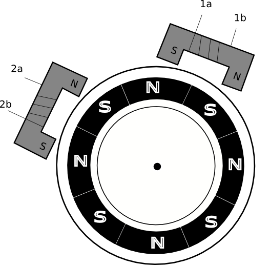
As you can see it has two coils and will normally therefore have 4 leads. If you have no documentation for your motor then you can just use a multimeter to work out each pair of pins. I.e. 1a and 1b will have a low resistance between them, and 2a and 2b will also have a low resistance. If you measure across two pins and have an infinite resistance then they are from different coils. So once you know which two pins are coil 1 and which are coil 2 then you will still need to find out which are ‘a’ and which are ‘b’ – but more on that later.
Bi-polar stepper motor driver
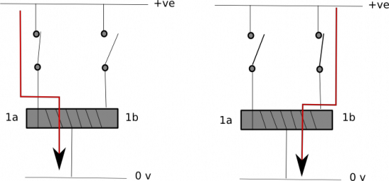
To drive the motor then let us consider one of the coils – say coil 1. In order to become an electromagnet we need to be able to change the direction of the current through the coil. So each side of the coil needs to be either or low.
If ’1a’ is high and ‘1b’ is low then we will have a current through the coil.
If ’1a’ is low and ‘1b’ is high then we will have a current through the coil in the opposite direction.
In the other two cases: where they are both high or both low, then no current flows and so it is no longer a magnet.
2. Uni-polar stepper motors
A uni-polar stepper motor looks like this:
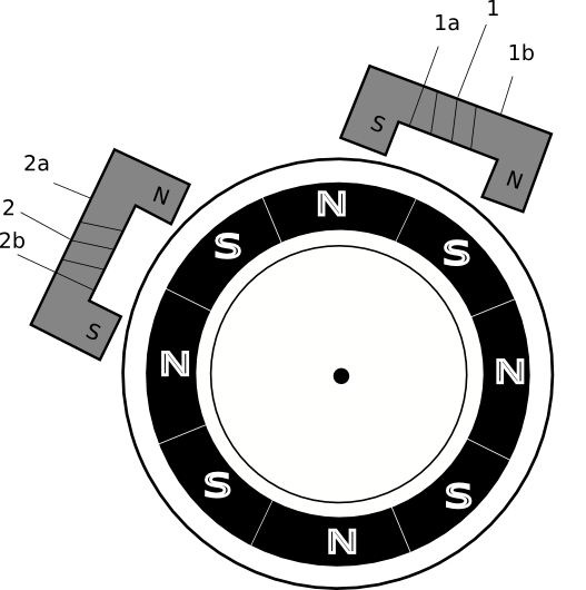
The only difference is that each of the coils now has 3 wires and will normally there have 6 leads. The new wire on each coil is called a ‘centre tap’ and is connected to the middle of the coil. Here also if one does not know which wire on the motor represents what then one can use multi-meter to check the connections. By checking for infinite resistance then you should be able to identify the leads that are for one coil, and the other leads for the other coil. Given a group of 3 leads you can tell which is the centre tap because, for coil 1, the resistance between ‘1a’ and the centre tap will be same as that between the centre tap and ‘1b’. The resistance between ‘1a’ and ‘1b’ will be double this value. NB the resistance tend to be very low, a few ohms, so you will need to select the appropriate resistance scale on your meter.
As mentioned earlier: we can drive a uni-polar motor ‘as if’ it was a bi-polar motor. To do this we have to just ignore the centre tap and then use the other two leads per coil as if it was a bi-polar.
Otherwise if we want to use the centre tap and, assuming we connect it to ground, then we will need two switches to dictate which direction the current flows through the coil.
Note that this mode of operation means that we are only using half of the coil in each direction. This will mean the ‘half coil’ only has half of the total resistance. Using Volts = Amps x Resistance (and assuming our supply voltage is the same) then if the resistance is halved then the current drain has doubled.
The price we pay is that we may be using twice as much current and because we are using half of the coil at a time then we may only get half the torque. Despite its name (uni versus bi) it sounds as if it is less capable but we can always use a uni-polar motor as if it was a bi-polar by ignoring the centre tap. So a uni-polar can be thought of as a bi-polar with extra choices.
Pulse Modes
As we have already mentioned – unlike a DC motor – one cannot just apply a fixed current and get to the motor to spin. Instead we need to supply pulses to the coils in a certain order. There are various ways to do this and each one has trade-offs to do with torque versus current consumption. So now we will look at the three different ways in which we can power up:-
1. The simplest ‘pulsing’ is called ‘Wave Drive’ and sets the coils as follows:-
T
T + 1
T +2
T + 3
1a
High
Low
Low
Low
1b
Low
Low
High
Low
2a
Low
High
Low
Low
2b
Low
Low
Low
High
This method only energises one coil at a time. So current consumptions is low. But equally the amount of torque is also low.
2. **This ‘pulsing’ method is called ‘Full Step Drive’.**
T
T + 1
T +2
T + 3
1a
High
High
Low
Low
1b
Low
Low
High
High
2a
Low
High
High
Low
2b
High
Low
Low
High
This method energises both coils at the same time- so requires twice the amount of current but provides about 40% more torque compared to Wave Drive. The other benefit of this method is that 1a is always the ‘inverse’ of 1b, and likewise 2a is always the ‘inverse’ of 2b. So we could control the motor with two output pins from the controller and, in our motor driver hardware, we could use an inverter between 1a-1b and another between 2a-2b.
3. The last pulsing method is called ‘Half Step Drive’ or ‘Micro-stepping’.
T
T+1
T+2
T+3
T+4
T+5
T+6
T+7
1a
High
Low
Low
Low
Low
Low
High
High
1b
Low
Low
High
High
High
Low
Low
Low
2a
High
High
High
Low
Low
Low
Low
Low
2b
Low
Low
Low
Low
High
High
High
Low
This method alternates between energising 2 coils and 1 coil. So the current requirements, and torque delivered, sit half way between ‘Wave Drive’ and ‘Full Step Drive’. It also helps to avoidance something called ‘resonance’ which can occur when using ‘Full Step Drive’ at certain speeds. The other side effect is to double the number of steps per revolution – which helps accuracy – but halves the overall maximum speed.
Control
A stepper motor can be controlled with the help of various IC chips. The simplest being the L293d.
Just like in the case of the dc motor, here we connect the 4 output pins of the L293d to the four ports 1a, 1b, 2a, 2b. Now we can connect the 4 input pins of L293d to a micro controller and control the motor as per our requirements. One major disadvantage of using L293d is that it can control one stepper motor only and that too bi-polar only, while there are a number of other IC’s which can control multiple steppers simultaneously.
One important thing to keep in mind is that one must know the motor frequency. For example if it is 300 Hz, then we know that it will take 3.33 milli-seconds to complete each step. Knowing this we can give as accurate timing as possible for the motor to turn as much as we require it to turn.
But what if one want to use the center tap of a uni-polar motor?
If one wants to use stepper motor as a uni-polar motor then one needs to use another hardware driver. The L293D contains ‘half H Bridges’ but what we actually need is effectively ‘ a quarter’ - known as a ‘Driver Array’. The ULN2003AN is a good choice. With the center tap connect to positive supply we can make the current flow in the coil by connect the ‘a’ terminal of the coil to ground. To make it flow the other way, then connect ‘b’ to ground. If both ‘a’ and ‘b’ then no current flows through the coil, and if both are low then the current flows both ways - which effectively cancels each other out. So we can do this by connecting one driver to the ‘a’ terminal and another to the ‘b’ terminal. So two drivers per coil makes four per motor. The ULN2003AN contains 7 drivers - so not quite enough to drive two motors from the one chip!
Note:
- Check the motor specifications carefully before buying like the stall torque, etc. one must ensure that the motor can fulfil the task it is being bought to accomplish.
-
Always use diodes between the motor and IC chip controlling the motor so as to ensure that if there is any back flow of current it does not affects the chip.
- Using a heat sink with the motor driver chip is also pretty useful.