Introduction
A lot of times when you deal with robotics, working only with +Vcc (Logic 1) and Ground (Logic 0) might not be enough. What if we have an analog input, i.e., value varies over a range, say 0V to +5V?
Then we require a tool that converts this analog voltage to discrete values. Analog to Digital Converter (ADC) is such a tool. In this tutorial, we shall learn the basic implementation of ADC in Atmel megaAVR devices in Single ended mode with code examples on ATmega16 to get started.
The ATmega16 ADC has 10-bit resolution. This means that an analog voltage between 0V and 5V will be encoded into one of 1024 binary representations via 8 channels that are port A pins from A0 to A7.
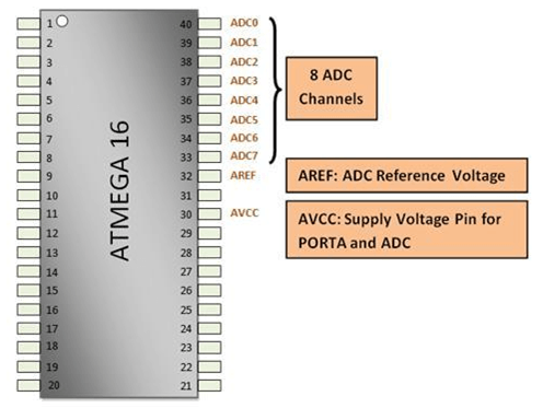
The reference voltage as shown in figure can be either less or equal to the supply voltage of the microcontroller.
This means that if you are using a 10 bit precision and 5V is the Vref, then, 0 corresponds to 0V, 1023 (2^10 - 1) corresponds to 5V. Similarly, the intermediate voltages correspond to their corresponding ADC value. So, what exactly is the output that we get from ADC?
ADC value is nothing but, the corresponding digital value given by:
ADC = Vin x 255 / Vref           #(8 bit)
ADC = Vin x 1023 / Vref          #(10 bit)
Registers
You need to declare certain registers before you initiate ADC specifying the conditions it needs to follow.
ADCSRA
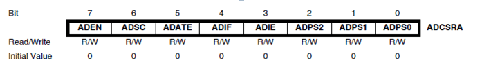
ADEN: ADC Enable bit, this bit must be set to 1 for turning ADC on.
ADSC: ADC Start Conversion bit, this bit is set to 1 to start ADC conversion, as soon as conversion is completed this bit is set back to 0 by the hardware.
ADATE: ADC Auto Trigger Enable, this bit is set to 1 to enable auto triggering of ADC conversion.
ADIF: ADC Interrupt Flag, this bit is set to 1 when ADC conversion gets complete.
ADIE: ADC Interrupt Enable, this bit is set to 1 if we want to activate the ADC conversion complete interrupt.
ADPS: ADC Prescaler bits, these bits are used to set the ADC clock frequency.
ADC clock frequency = XTAL frequency / Prescaler
The ADC clock frequency must lie somewhere between 50 kHz to 200 kHz to get maximum resolution. If ADC resolution of less than 10 bits required, then the ADC clock frequency can be higher than 200 kHz. At 1 MHz it is possible to achieve eight bits of maximum resolution.
In the microcontroller we’re discussing, prescaler values of 2, 4, 8, 16, 32, 64 & 128 are provided. A typical core clock speed is 16 MHz. So if you are running your AVR board at 16 Mhz, you can set the ADC clock to one of the following values:
16 MHz / 2 = 8 MHz
16 MHz / 4 = 4 MHz
16 MHz / 8 = 2 MHz
16 MHz / 16 = 1 MHz
16 MHz / 32 = 500 kHz
16 MHz / 64 = 250 kHz
16 MHz / 128 = 125 kHz
Since the ADC clock needs to be between 50 kHz & 200 kHz for 10 bit accuracy, we can only use the 128 prescaler and achieve a 125 kHz ADC clock.
ADMUX
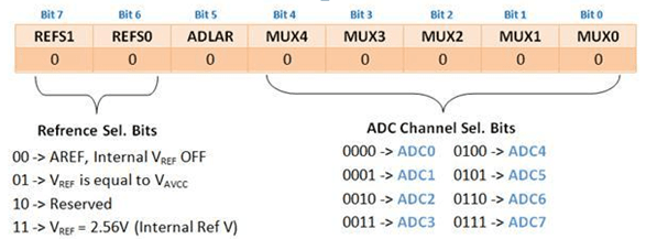
REFS: REFS1 and REFS0 bits determine the source of reference voltage whether it is internal or the external voltage source connected to AREF pin.
MUX: MUX bits are used to select between the channels which will provide data to ADC for conversion.
ADLAR: ADLAR bit when set to 1 gives the left adjusted result in data registers ADCH and ADCL. These help to get the required precision in the output.
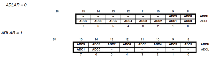
When ADCL is read, the ADC Data Register is not updated until ADCH is read. Consequently, if the result is left adjusted and no more than 8-bit precision is required, it is sufficient to read ADCH. Otherwise, ADCL must be read first, then ADCH.
Code
The following code has used an 8-bit precision. Where, the input is constantly at Pin A0. The 8 bit output is stored in PORT B.
#define F_CPU 16000000UL

#include <util/delay.h>
#include <avr/io.h>

int main(void)
{
    //Declaring Port A as input
    DDRA=0;

    //Declaring port B as output
    DDRB=255;

    // Enabled ADC and set prescaler division factor as 128
    ADCSRA|=(1<<ADEN)|(1<<ADPS2) |(1<<ADPS1) |(1<<ADPS0);

    //Vref is same as Vcc, Input constantly at Pin 0 of port A and Setting ADLAR to 1 left shifts the bits for an 8-bit precision
    ADMUX|=(0<<REFS1)|(1<<REFS0)|(0<<MUX4)|(0<<MUX3)|(0<<MUX2)|(0<<MUX1)|(0<<MUX0)|(1<<ADLAR);

    while(1) {
        //Start ADC
        ADCSRA|=(1<<ADSC);

        //Do nothing till the conversion is over. Here, the condition that ADSC is cleared after conversion has been used. You can also use ADIF
        while((ADCSRA& (1<<6))!=0);

        //The ADC value stored in ADCH has been sent to PORT B as output.
        PORTB = ADCH;

        _delay_ms(100);
    };
}
For a small demonstration, you can connect pin A0 to a powered potentiometer and vary its resistance to get ADC values of intermediate voltages. You can display this output on LCD display or you can even display it’s binary output on LEDs.