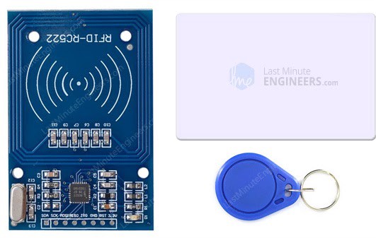
The RC522 RFID module based on MFRC522 IC from NXP is one of the most inexpensive RFID options. It usually comes with an RFID card tag and key fob tag having 1KB memory. And best of all, it can write a tag.
Working
The RC522 RFID Reader module is designed to create a 13.56MHz electromagnetic field that it uses to communicate with the RFID tags (ISO 14443A standard tags). The reader can communicate with a microcontroller over a 4-pin Serial Peripheral Interface (SPI) with a maximum data rate of 10Mbps. It also supports communication over I2C and UART protocols.
The module comes with an interrupt pin. It is handy because instead of constantly asking the RFID module “is there a card in view yet? “, the module will alert us when a tag comes into its vicinity.
The operating voltage of the module is from 2.5 to 3.3V, but the logic pins are 5-volt tolerant, so it can be easily connected to an Arduino or any 5V logic microcontroller without using any logic level converter.
RC522 RFID Module Pinout
The RC522 module has a total of 8 pins that interface it to the outside world. The connections are as follows:
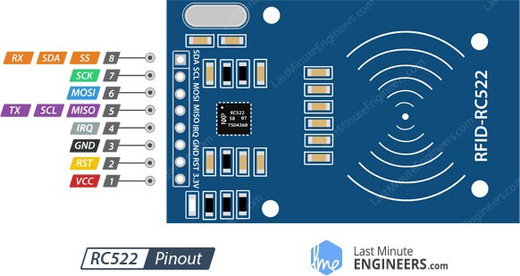
VCC supplies power for the module. This can be anywhere from 2.5 to 3.3 volts. It can be connected to 3.3V output from the Arduino.
RST is an input for Reset and power-down. When this pin goes low, hard power-down is enabled. This turns off all internal current sinks including the oscillator and the input pins are disconnected from the outside world. On the rising edge, the module is reset.
GND is the Ground Pin and needs to be connected to the GND pin on the Arduino.
IRQ is an interrupt pin that can alert the microcontroller when an RFID tag comes into its vicinity.
MISO / SCL / Tx pin acts as Master-In-Slave-Out when SPI interface is enabled, acts as serial clock when I2C interface is enabled and acts as serial data output when UART interface is enabled.
MOSI (Master Out Slave In) is SPI input to the RC522 module.
SCK (Serial Clock) accepts clock pulses provided by the SPI bus Master i.e. Arduino.
SS / SDA / Rx pin acts as Signal input when SPI interface is enabled, acts as serial data when I2C interface is enabled and acts as serial data input when UART interface is enabled. This pin is usually marked by encasing the pin in a square so it can be used as a reference for identifying the other pins.
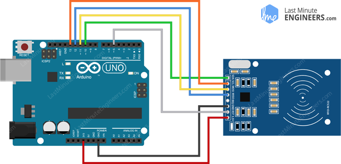
Wiring
To start hooking up the Arudino, connect the VCC pin on the module to 3.3V on the Arduino and GND pin to ground. The pin RST can be connected to any digital pin on the Arduino. In this case, it’s connected to digital pin #5.
Each Arduino Board has different SPI pins which should be connected accordingly. Each Arduino Board has different SPI pins which should be connected accordingly.
Arduino Code - Reading
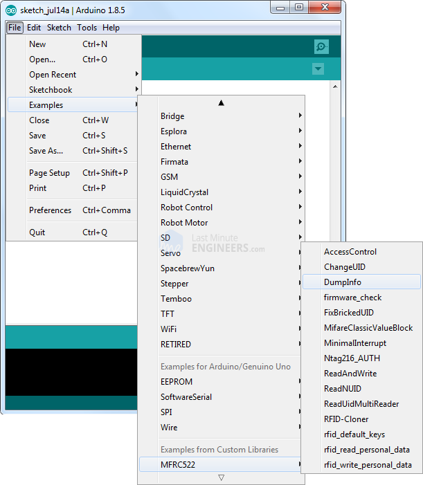
There’s a library called MFRC522 library which simplifies reading from and writing to RFID tags. Once the library is installed, open Examples submenu and select MFRC522 > DumpInfo example sketch.
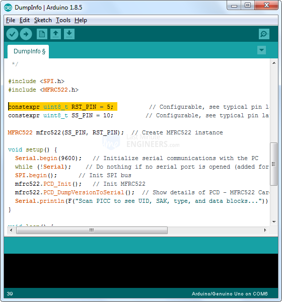
This sketch will not write any data to the tag. It just tells us if it managed to read the tag, and displays some information about it.It should be made sure that the RST_PIN is correctly initialized.
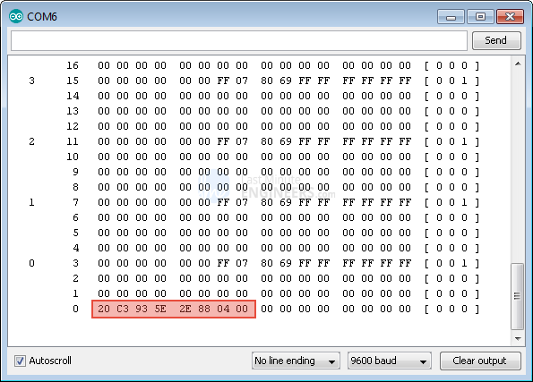
Now the sketch is uploaded and the Serial Monitor is opened. On bringing the tag closer to the module, this is seen on the monitor.
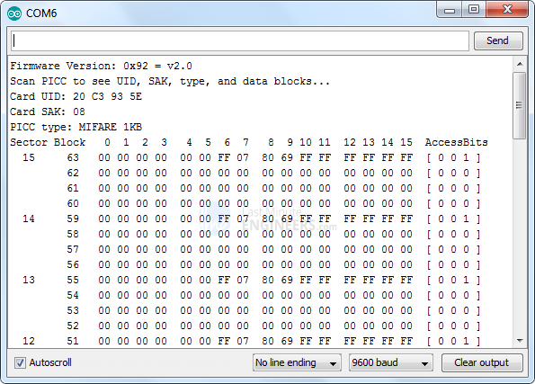
It displays all the useful information about the tag including tag’s Unique ID (UID), the memory size and the whole 1K memory.
MIFARE Classic 1K Memory Layout
The 1K memory of the Tag is organized in 16 sectors (from 0 to 15) Each sector is further divided into 4 blocks (block 0 to 3). Each block can store 16 bytes of data (from 0 to 15).
16 sectors x 4 blocks x 16 bytes of data = 1024 bytes = 1K memory
The whole 1K memory with sectors, blocks and data is highlighted below.
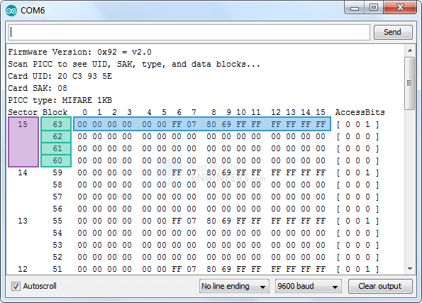
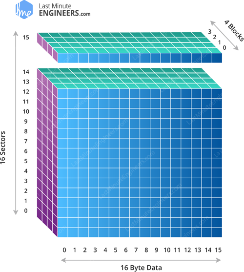
The Block 3 of each sector is called Sector Trailer and contains information called Access Bits to grant read and write access to remaining blocks in a sector. That means only the bottom 3 blocks (block 0, 1 & 2) of each sector are actually available for data storage. Also The Block 0 of sector 0 is known as Manufacturer Block/Manufacturer Data contains the IC manufacturer data, and the Unique IDentifier (UID). The Manufacturer Block is highlighted in red below.
Arduino Code - Writing
Below is a sketch that will do a basic demonstration of writing custom data to RFID tag.
#include <SPI.h>      //include the SPI bus library
#include <MFRC522.h>  //include the RFID reader library

#define SS_PIN 10  //slave select pin
#define RST_PIN 5  //reset pin

MFRC522 mfrc522(SS_PIN, RST_PIN);  // instantiate a MFRC522 reader object.
MFRC522::MIFARE_Key key;          //create a MIFARE_Key struct named 'key', which will hold the card information

//this is the block number we will write into and then read.
int block=2;

byte blockcontent[16] = {"Last-Minute-Engg"};  //an array with 16 bytes to be written into one of the 64 card blocks is defined
//byte blockcontent[16] = {0,0,0,0,0,0,0,0,0,0,0,0,0,0,0,0};  //all zeros. This can be used to delete a block.

//This array is used for reading out a block.
byte readbackblock[18];

void setup()
{
    Serial.begin(9600);        // Initialize serial communications with the PC
    SPI.begin();               // Init SPI bus
    mfrc522.PCD_Init();        // Init MFRC522 card (in case you wonder what PCD means: proximity coupling device)
    Serial.println("Scan a MIFARE Classic card");

  // Prepare the security key for the read and write functions.
  for (byte i = 0; i < 6; i++) {
    key.keyByte[i] = 0xFF;  //keyByte is defined in the "MIFARE_Key" 'struct' definition in the .h file of the library
  }
}

void loop()
{
  // Look for new cards
  if ( ! mfrc522.PICC_IsNewCardPresent()) {
    return;
  }

  // Select one of the cards
  if ( ! mfrc522.PICC_ReadCardSerial())
  {
    return;
  }
    Serial.println("card selected");

   //the blockcontent array is written into the card block
   writeBlock(block, blockcontent);

   //read the block back
   readBlock(block, readbackblock);
   //uncomment below line if you want to see the entire 1k memory with the block written into it.
   //mfrc522.PICC_DumpToSerial(&(mfrc522.uid));

   //print the block contents
   Serial.print("read block: ");
   for (int j=0 ; j<16 ; j++)
   {
     Serial.write (readbackblock[j]);
   }
   Serial.println("");
}

//Write specific block
int writeBlock(int blockNumber, byte arrayAddress[])
{
  //this makes sure that we only write into data blocks. Every 4th block is a trailer block for the access/security info.
  int largestModulo4Number=blockNumber/4*4;
  int trailerBlock=largestModulo4Number+3;//determine trailer block for the sector
  if (blockNumber > 2 && (blockNumber+1)%4 == 0){Serial.print(blockNumber);Serial.println(" is a trailer block:");return 2;}
  Serial.print(blockNumber);
  Serial.println(" is a data block:");

  //authentication of the desired block for access
  byte status = mfrc522.PCD_Authenticate(MFRC522::PICC_CMD_MF_AUTH_KEY_A, trailerBlock, &key, &(mfrc522.uid));
  if (status != MFRC522::STATUS_OK) {
         Serial.print("PCD_Authenticate() failed: ");
         Serial.println(mfrc522.GetStatusCodeName(status));
         return 3;//return "3" as error message
  }

  //writing the block
  status = mfrc522.MIFARE_Write(blockNumber, arrayAddress, 16);
  //status = mfrc522.MIFARE_Write(9, value1Block, 16);
  if (status != MFRC522::STATUS_OK) {
           Serial.print("MIFARE_Write() failed: ");
           Serial.println(mfrc522.GetStatusCodeName(status));
           return 4;//return "4" as error message
  }
  Serial.println("block was written");
}
The sketch starts with including the MFRC522 and SPI library, defining Arduino pins to which RC522 is connected and instantiating MFRC522 reader objects.Next, a block in which we are going to store the data has to be defined. Here sector 0 block 2 is selected, since writing into ‘sector trailer’ block can make the block unusable. Next, an array of 16 bytes named blockcontent[16] is defined which holds the message to write into the block. Next, an array of 18 bytes named readbackblock[18] has to be defined. This can be used to read the written contents back. The MIFARE_Read method in MFRC522 library requires a buffer that is at least 18 bytes to hold the 16 bytes of a block.
In loop function: first scanning is done to see if there is a card in view, if yes, that card is selected for writing and reading purposes.
Checking the success of the operation can be done using custom function called readBlock() which again takes two parameters — one is block number and other is array to store block contents. Finally, the contents of readbackblock array using a for loop are printed and displayed on the serial monitor.
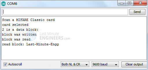
The output on the serial monitor will look like this.