In this tutorial, we’ll make a simple line follower which follows a white line on a black surface or vice-versa using simple basic components.
Things Required:
- Sensor pairs (either LED-LDR or IR LED-Photodiode) (2)
- 10k Ohm Potentiometers (4)
- 1k Ohm resistors (4)
- LM358N dual amplifier IC (1)
- BC547 npn BJT (2)
- B557 pnp BJT (2)
- Flyback diodes (2)
- 8 pin IC base for your LM358
- PCB, relimates
- A differential drive chasis
We’ll be basically dealing with two circuits here.
i) Sensor Circuit
ii) Comparator-bjt circuit
Sensor Circuit
The sensor circuit will basically tell you whether your robot is on the line or out of line. The sensors suitable for this purpose are LED-LDR sensor, or IR LED-Photodiode sensor pair.
Click here to understand the basics of these sensor pairs.
Now, let us see how it’ll help to differentiate the line from the surface. We know the fact that a white surface will anytime reflect more rays than a black surface. This is the basic principle that we use to judge whether the sensor pair is on white line or black line.
Consider this LED-LDR sensor pair.
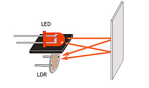
Now, when this sensor pair is on a white line,
=> more led light reflected by the surface
=> more light falls on LDR
=> lesser LDR resistance
=> the voltage across LDR will be less
Similarly, when the sensor pair is on a black line,
=> the voltage across LDR will be high.
Similarly, for the IR LED-Photodiode sensor pair,
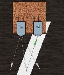
The voltage across the IR Photodiode will vary as per the intensity of light falling on it.
More the reflected light, lesser the voltage across ir receiver.
Here is your sensor circuit:
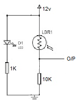
The 10k component is your potentiometer which you might have to set to the maximum range. This resistance, ideally should be near ( R(light) * R(dark) )^1/2 where, R(light) is the approximate resistance of LDR during light and R(dark) is the resistance of the same in dark.
Comparator Circuit
Now for analysing the sensor output, we use a comparator to get a digital output.
Click here to understand the basics of comparators.
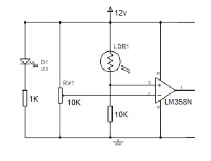
Now, the LED-LDR is connected to a comparator LM358. LM358 is an operational amplifier IC which is being used as a comparator. The non inverting terminal of op-amp (The + terminal) reads the voltage across resistor R4. And, the inverting terminal of op-amp (The - terminal) reads the voltage that has been set at the potentiometer.
When on white line, V(ldr) less => V(R4) more.
When on black line, V(ldr) more => V(R4) less.
The voltage of at potentiometer (- terminal), V(pot) is such that :
V(R4)white > V(pot) > V(R4)black
Such a voltage is set be setting up the corresponding potentiometer resistance.
Hence, now
When sensor on white line :
V(R4)white > V(pot)
=> V+ > V-
=> Op-amp output = High
When sensor on black line :
V(pot) > V(R4)black
=> V- > V+
=> Op-amp output = Low
This is how we know whether the sensor is on black or white line.
So, if one end of the motor is connected to 12 V and the other end is connected to the Op-amp output, you’ll be able to run the motor or stall the motor depending on which surface your sensor(LED-LDR pair) is.
When white,
Potentials across motor : 12-12
=> stall condition
When black,
Potentials across motor : 12-0
=> motor runs
Now, how do we implement this on our line follower?
In this tutorial, we’ll be making a 2 sensor line follower which will be working as -

For the turns, we have one motor stalled and other running.
Here is the complete line follower circuit:

Here, we have both the sensor and the op-amp circuit at 12 V Vcc . That is why, the resistances attached with led and ldr as as high as 1k and 10k respectively.
You can observe the components, BC547, B557. These are transistors called the Bi-polar Junction transistors This is to increase the amount of current coming from the output of the op amp so as to fulfill the current requirements of the DC motor and also to ensure either high or low voltages at any point of time during the run. Hence, the BJTs ensure no floating voltage at any point of time. This set up of NPN and PNP transistors is known as push-pull circuit.
And the diode across the motor is a flyback diode to prevent reverse current.
Here are the actual images of circuits and robot:
.

Sensor circuit, which was attached to the lower part of the chasis.

Op-amp circuit whose output is forwarded to the bjt circuit

BJT circuit.

Assembled bot.