Author : Vraj Parikh
Kraig 103 and Kraig 104 were mainly hands on sessions for the skills required to make a robosoccer robot i.e. soldering and control box. The classes also dealt with the important concept of rectifiers.
Kraig 103 started off where Kraig 102 had left i.e. control box circuit. The doubts that many students had pertaining to the above stated topic were cleared. It was followed by the division of class into 6 parts wherever there was a working power socket so that the soldering irons could be plugged.
P.C.B. Soldering is a process which involves making a blob of solder on each of the dot of the P.C.B. and then joining the blobs together to form a straight continuous line. The correct method of doing so is to hold the tip of the soldering iron at 45° angle from the P.C.B. and then bring the solder wire into contact so that it melts and falls on the desired place. After repeating this for desired number of dots they are connected by melting some solder wire between two consecutive blobs and connecting them. This works as the solder being an alloy of tin and lead has comparatively low melting point. It was also prescribed that some solder wire should first be melted on the tip of a new soldering iron to ensure that the solder then sticks to the different metal on the P.C.B. After explaining this all present students got a chance to practice soldering and they were asked to try and solder two lines on the P.C.B. as near as possible. This concluded Kraig 103.
Kraig 104 started off with teaching about rectifiers which are an effective replacement of adapters. They convert A.C. voltage into regulated D.C voltage. A rectifier uses the polar property of a diode i.e. a diode allows only unidirectional current to pass through it which happens when the P- terminal is at higher voltage then the N- terminal of the diode. This configuration is known as forward bias of the diode. The following shows a basic circuit for the rectifier circuit.
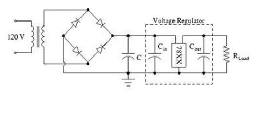
The diodes at the right top and left bottom are in forward bias in the positive half cycle and the diodes at the left top and the bottom right are in forward bias in the negative half cycle of the voltage. Hence current always flows in one direction in the circuit. The first capacitor is known as filter which converts the varying signals (as shown below) to ripple voltage.
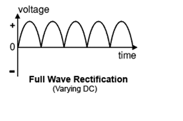
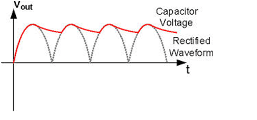
Fig 1 shows voltage after only rectifier and fig 2 shows voltage after filtering the voltage using a capacitor. The filtering works on the property of capacitor to store charge when voltage across terminals is increasing and give it away when the reverse happens i.e. the voltage across its terminals decreases.
This is followed by a 78xx I.C. which is voltage regulator, where xx denotes its output voltage. It removes the ripples from the voltage and the voltage looks like:
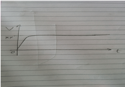
Hence we arrive at a regulated voltage as we wished to. The capacitor after this I.C. is used to take away whatever little ripples are left.
With this, the topic of the rectifier circuit was concluded.
After this the class was asked to do soldering practice in case somebody had not done so previously.
This concluded the Kraig 104 session. The audience left the hall fascinated and all the inquisitive students had their thirst of knowledge fulfilled!