Tools:
- Soldering Iron
- Laptop
- AVR related programming software
Materials:
- LEDs
- LDRs
- 2 Wheels
- Metal Chasis
- 1 Castor Wheel
- 2 DC motors
- 1 Development Board
- 1 Microcontroller (Atmega 16)
- Motor Driver (L293D)
- Relimates
- Potentiometers
Problem Statement of Lumos:
Build one or more autonomous robot(s) that can differentiate between number of light sources of similar intensity kept inside an isolated room (Arena) and turn each one off.
In this DIY we will learn how to detect and navigate the bot towards the light source of maximum intensity which in our case is the light source closes to the bot.
For this DIY, let us divide the discussion into 3 parts. The locomotion, sensors and processing.
Locomotion:
_**_The locomotion system we are using here is the differential drive. It is a basic design with two motors, two wheels and a castor wheel. The chassis is a ready-made steel chassis that can be bought of the internet.
[caption id=”attachment_450” align=”aligncenter” width=”300” caption=”Fig: Chassis for the differential Drive”]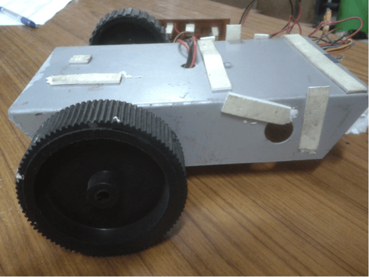 [/caption]
[caption id=”attachment_450” align=”aligncenter” width=”300” caption=”Fig: Rectifier Circuit with 7805 and 7812 ICs”]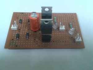 [/caption]
Sensor:
_**_This is the most important part of the robot. We have used here a three sensor layout which enables the robot to sense any light source in front of it. Of course, there can be several more different layouts to optimize the performance of the robot. Below is the picture of the sensory circuit mounted on the robot.
[caption id=”attachment_455” align=”aligncenter” width=”300” caption=”Fig: Sensor circuit and its placement on the chassis”]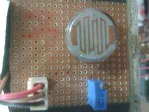 [/caption]
[caption id=”attachment_454” align=”aligncenter” width=”300” caption=”Fig: Sensor circuit and its placement on the chassis”]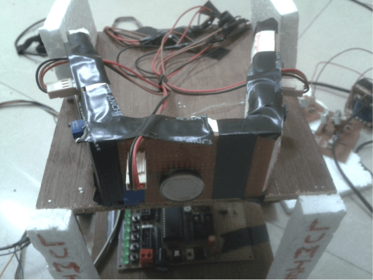 [/caption]
Let us mark these sensors as left(L), right(R) and centre(C) sensors. The ultimate goal of our code is to find which sensor receives maximum intensity and to face the robot in that direction. Below diagram shows the circuitry in the sensor circuits:
[caption id=”attachment_453” align=”aligncenter” width=”300” caption=”Fig: Circuitry of the sensor circuit”]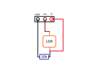 [/caption]
Each sensor has to be provided a 5V Vcc supply and a data(D) output has to be taken out from it. Three sensor circuits as shown in fig 2 will complete our sensory part of the robot.
Processing:
We are here using an Atmega 16A microcontroller running at 16Mhz. The development board and programmer that are used here are available at www.robokits.in. Of course there are several other sites too from where development boards and programmers can be acquired.
[caption id=”attachment_450” align=”aligncenter” width=”300” caption=”Fig: Development Board for the microprocessor”]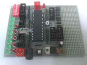 [/caption]
For the basics regarding the Atmega 16A microcontroller, refer to its datasheet which is available online.
So let’s get down to the connections. Here we have 3 sets of inputs coming from the 3 sensors. As these are analog signals, in order to process them, we need to provide this input to the Analog-to-Digital converter or the ADC. The ADC on the Atmega is located on the Port A. So the inputs from the sensors go to the first three pins of Port A( PA0, PA1, PA2, PA3). Now as the LED array on the development board is attached to the Port B, we will be using this port as the output from the microcontroller. From the microcontroller, the outputs have to go to the motor driver circuit which is used to run the motors.
As the motor driver consists of two enable pins we have to provide a high to both these pins. So we use the pins PB0 and PB1 to do this. The other 4 inputs to the motor driver we provide using the pins PB3, PB4, PB5, and PB6. Below is a circuit diagram showing the connections for a motor driver circuit.
[caption id=”attachment_456” align=”aligncenter” width=”300” caption=”Fig: Connections of a motor driver IC L293D”]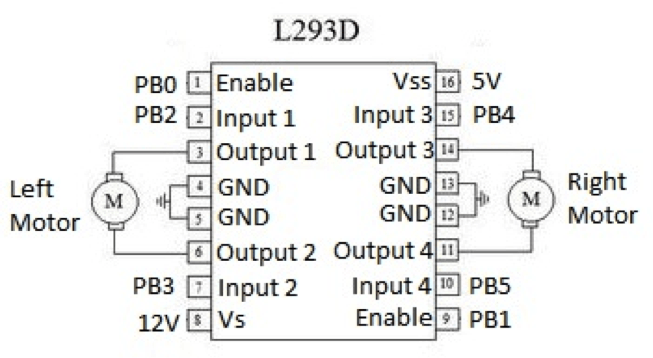 [/caption]
[caption id=”attachment_456” align=”aligncenter” width=”300” caption=”Fig: Motor driver IC L293D Circuit”]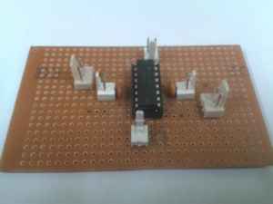 [/caption]
The voltage supply at Vs is used for running the 12V 100rpm motors while the 5V supply at Vss is used for powering the internal circuitry of the IC. Here one can easily see that according to these connections, the robot follows the following motions:
| PB2 | PB3 | PB4 | PB5 | Motion |
| 1 | 0 | 1 | 0 | Forward |
| 0 | 1 | 0 | 1 | Backward |
| 0 | 1 | 1 | 0 | Left |
| 1 | 0 | 0 | 1 | Right |
So now we get to the data processing. As mentioned earlier our aim is to identify which LDR gets the maximum intensity of light. As the intensity increases the resistance decreases. From the circuit diagram of our sensor circuit it can be seen that as the light intensity increases(Resistance decreases) the voltage given at the D terminal will increase with respect to the ground. Once you understand the previous line it is easy to figure out that the LDR having maximum light falling on it will give an output D of maximum voltage with respect to the ground.
So our algorithm for this should go as follows(L, R and C representing the various voltage outputs of the sensors):
If(L greater than R and L greater than C)

Turn left

Else If(R greater than C and R greater than L)

Turn right

Else If(C greater than L and C greater than R)

Go forward
The actual code to be burnt into the microcontroller is:
#include

int a[3];             //Array to store the sensor voltages

int main(void)

{

DDRA=0x00;            //Set port A to input
DDRB=0xff;            //Set port B to output
while(1)
{

ADMUX=0b01100000;
int i;
for(i=0;ia[1] && a[0]>a[2])         //left sensor highest

PORTB=0b00100111;     //Turn left

else

if(a[0]a[2])          //Centre sensor highest

PORTB=0b00101011;     //Go straight

else

if(a[0]==a[1]) //Any two sensors getting same value, then go straight

PORTB=0b00101011;

else

if(a[1]==a[2])
PORTB=0b00101011;
else
if(a[2]>a[1] && a[2]>a[0])                 //Right sensor highest
PORTB=0b00011011;            //Turn right
}
return 0;
}